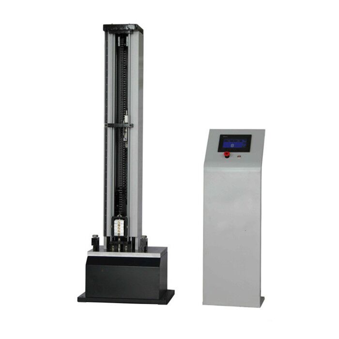
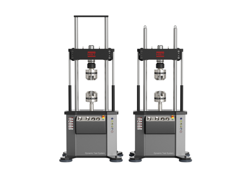


GLY Series Optical Fiber Cable Tensile & Crush Testing Machine
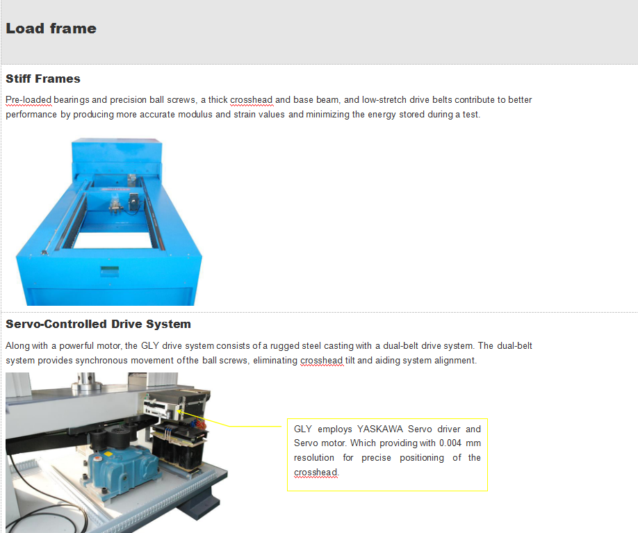
These machines offer force, displacement or deformation closed loop testing. The load frames are rigid constructed, providing superior axial and lateral stiffness.
Standards:
ISO 7500-1, EN 10002-2, ASTM E4, JIS B7721 ASTM E83, ISO 9513, and EN 10002-4
Request A Quote Files DownloadGLY Series Optical Fiber Cable Tensile & Crush Testing Machine
These machines offer force, displacement or deformation closed loop testing. The load frames are rigid constructed, providing superior axial and lateral stiffness.
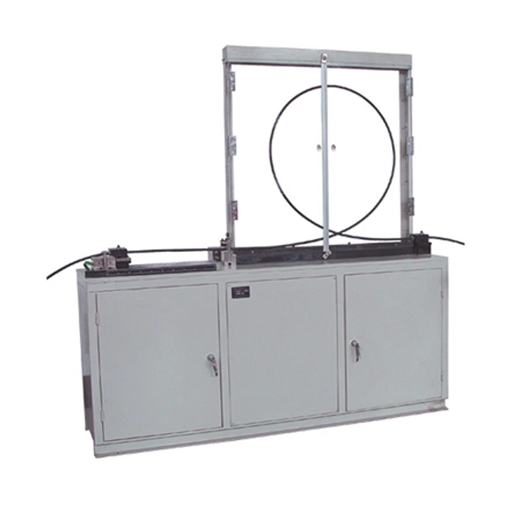
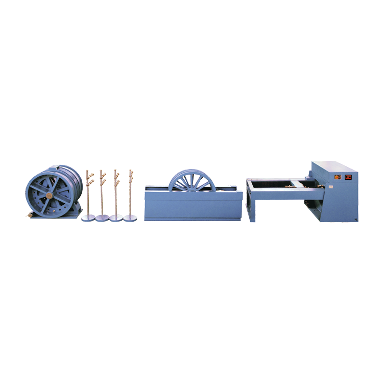
Method E1: Tensile performance
This measuring method applies to optical fiber cables which are tested at a particular tensile strength in order toexamine thebehavior of the attenuation and/or the fiber elongation strain as a function of the load on a cable which may occurduring
installation. This method is intended to be non-destructive (the tension applied shall be within the operational values).
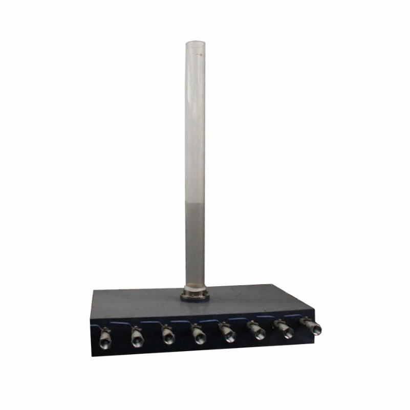
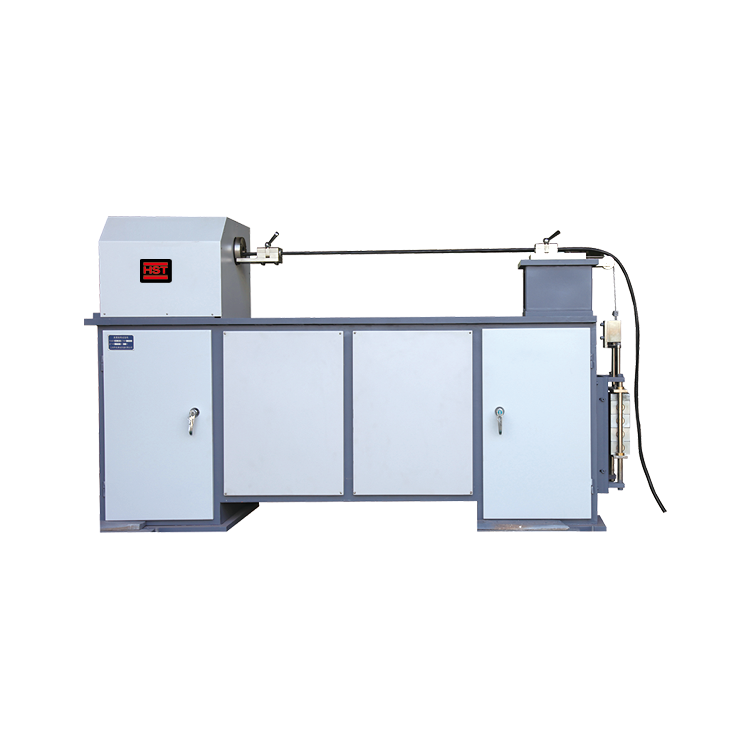
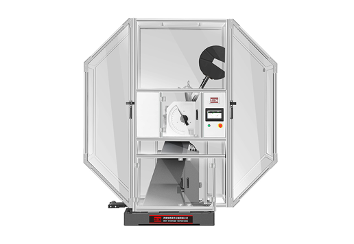
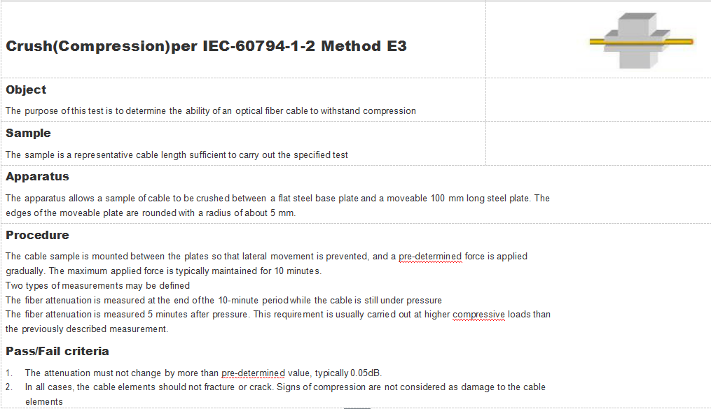
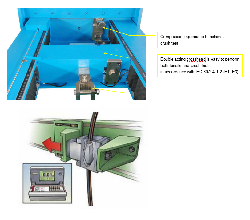
Method E3: Crush
The purpose of this test is to determine the ability of an optical fiber cable to withstand crushing.
|
Applications |
|
Tensile performance Per IEC-60794-1-2 Method E1 |
|
Object |
| Mainspecifications | |
| Load capacity: | 100kN for tension, 10kN for crush test |
| Accuracy class: | ±1% |
| Measuring range: | 1%-100% |
| Crush platen: | 100mm×100mm,hardness:HB240~280 |
| loading speed: | 0.2~300mm/min |
| Deformation measuring accuracy: | ±0.5% |
| Displacement measuring accuracy: | ±0.3% |
| Elongation measurement: |
1. gauge length:1000mm 2. Measuring resolution is better than 10μm 3. Accuracy is better than ±0.5%. |
| Crosshead travel: | 800~1100mm |
|
4. General Specifications 5. Load Measurement Accuracy: 6. ±1% of reading to 1/100 of load weighing system capacity meets or exceeds the requirements of the following standards: ISO 7500-1, EN 10002-2, ASTM E4, JIS B7721. 7. Strain Measurement Accuracy: 8. ±0.5% of reading to 1/50 of full scale with most ASTM E83 class B or ISO 9513 class 0.5 extensometers meets or exceeds ASTM E83, ISO 9513, and EN 10002-4. 9. Speed Accuracy: 10. Set speed<0.05% Max. speed: ±1% Set speed ≥0.05% Max. speed:±0.5% 11. Position measurement accuracy: 12. ±0.01% of reading or 0.0001 mm, whichever is greater 13. Power supply: 14. Standard optional voltages 220/240VAC, 50-60 Hz, Power must be free of spikes and surges exceeding 10% of the nominal voltage. 15. Operating Temperature: 16. 0 to +38°C (+32 to +100°F) 17. Humidity Range: 18. 10% to 90% non-condensing, 19. Storage Temperature: 20. -40 to +66°C (-40 to +150°F) 21. Note: 22. Extra wide and/or extra height frames are available. 23. Power supply system is completely customizable. 24. Specifications are subject to change without notice. |
|
Relate Products